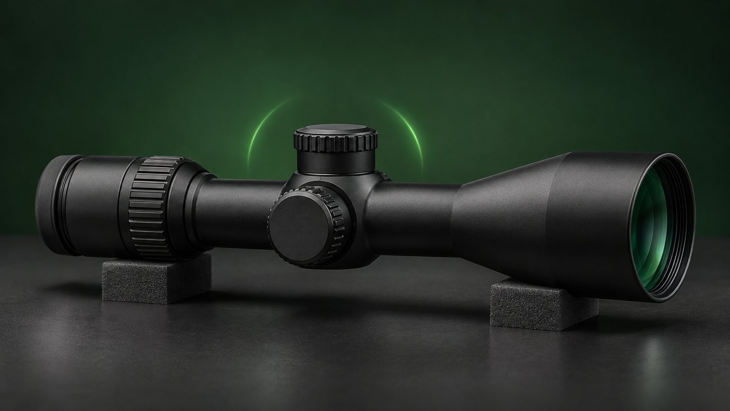
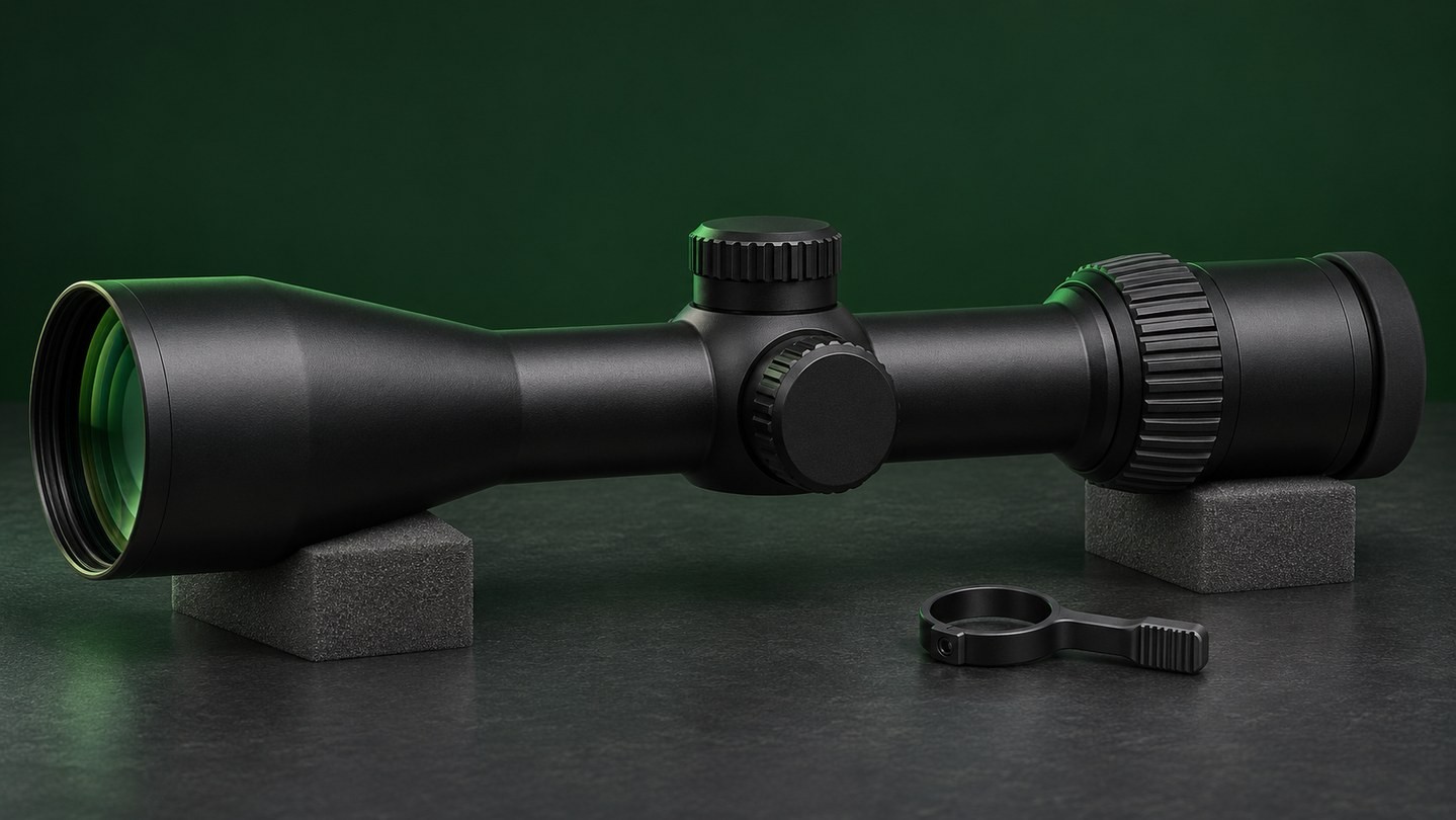
Turn a rifle scope's power ring and the target appears larger. Turn an elevation or windage turret and the aiming relationship changes. Both actions affect components hidden inside the main tube, but they do not move the same parts in the same way.
The internal assembly involved is commonly called the erector system, erector tube, inverting system or reversal system. The exact terminology and construction vary by manufacturer, yet the basic jobs are similar: present the image in the correct orientation, provide magnification in a variable-power design, and allow the optical axis to be adjusted.
Understanding those jobs helps explain several specifications that are otherwise easy to misread. It also shows why main-tube diameter, reticle focal plane and adjustment range are related—but are not interchangeable measures of quality.
Start with the complete optical path
A riflescope does not magnify an image with one lens. Light first enters through the objective lens, which forms an intermediate image inside the optic. That initial image is inverted. Internal lens groups then turn it to the correct orientation and, in a variable-power scope, change its apparent size. Finally, the ocular or eyepiece presents the image to your eye.
Each stage has a different job. The front objective does not simply “collect magnification,” and the rear eyepiece does not create the entire power range by itself. Our guide to the objective and ocular lenses explains the two ends of the system in more detail.
The reticle is placed at one of the image planes along this path. Its position relative to the variable magnification system determines whether it appears to change size as magnification changes.
What is the erector system?
The erector system is the internal optical and mechanical assembly that handles image orientation and, in many variable scopes, magnification. It normally sits inside the scope's main tube. Some manufacturers describe the complete movable inner assembly as the erector tube, while others use inverting system or reversal system for the lens group.
It is helpful to separate three related ideas:
- Erecting or reversing the image: internal lenses turn the objective's inverted image into the upright view seen by the user.
- Changing magnification: moving lens groups alter the scale of the image in a variable-power scope.
- Changing the optical alignment: elevation and windage mechanisms move or tilt the internal assembly by a very small amount.
Those functions may be integrated into one compact mechanism, but they should not be treated as one simple lens sliding back and forth. The exact number of elements, their spacing, the reticle location and the support system are design-specific.
Why the image needs to be turned upright
A positive objective lens forms a real image that is upside down and laterally reversed at the first image plane. That behavior is normal optics, not a defect. Without an erecting system, the view reaching the eyepiece would have the wrong orientation.
The internal reversing lens group forms another image in the correct orientation. The eyepiece then works much like a magnifier, presenting that image to the eye at a comfortable apparent distance.
This is why the word erector is used: the system erects, or rights, the image. A fixed-power scope still needs an optical arrangement that delivers an upright image even though it does not need a user-adjustable zoom range.
How the power ring changes magnification
In a variable-power scope, turning the power selector moves internal zoom elements through a controlled path. Changing the spacing between those lens groups changes how large the intermediate image appears at the eyepiece.
The movement has to remain aligned across the entire zoom range. A smooth external power ring is only the control surface; it does not reveal how many internal groups move or how the manufacturer guides them. Two scopes with the same printed magnification range can use different optical layouts, cam paths and mechanical supports.
Magnification also changes other parts of the viewing experience. Field of view generally becomes narrower as power rises, exit pupil becomes smaller for a given objective diameter, and eye-position tolerance can feel less forgiving. Those effects are connected to the complete optical design, not just the power ring.
How elevation and windage adjustments affect the system
Elevation and windage turrets do not normally move the entire outer scope body. Instead, their mechanisms apply minute changes to the internal optical assembly. Depending on the design, the erector assembly tilts or shifts against a spring or another return mechanism.
That small internal angular change alters the relationship between the optical line of sight and the reticle. The engraved direction on a turret is normally expressed as the intended point-of-impact direction, but the mechanical movement inside the scope may appear opposite if viewed in isolation.
Available movement is finite. Once the internal assembly approaches the edge of its mechanical range, less travel may remain in that direction—and movement on the other axis can also become more limited. This is one reason the published total range is not the same as the elevation remaining after a scope has been mounted and zeroed. See our guide to total versus usable adjustment travel.
Why reticle position changes FFP and SFP behavior
The erector or inverting system creates two useful image planes. A reticle can be placed before the variable magnification group or after it.
With a first focal plane (FFP) reticle, the reticle is located on the objective side of the variable magnification system. The image and reticle appear to grow or shrink together, so their angular relationship remains consistent through the magnification range.
With a second focal plane (SFP) reticle, the reticle is located on the eyepiece side of the variable magnification system. The target image changes apparent size while the reticle appears to remain the same size. Reticle-based measurements are therefore usually calibrated for a specified magnification.
Neither arrangement is automatically superior. They change visibility, subtension behavior and how the reticle feels at low and high power. Our FFP versus SFP guide covers the practical comparison.
What main-tube diameter can change
The main tube is the outer structure around much of the erector assembly. A larger diameter can give the designer more physical room for internal movement, supports and adjustment geometry. That may help a particular design provide a wider adjustment range.
But diameter is design potential, not a performance certificate. A 34 mm scope does not automatically have more usable travel than every 30 mm scope, and a 30 mm tube does not inherently transmit more light than a 1-inch tube. Lens diameter, optical layout, coatings, internal apertures and mechanical choices all matter.
Tube diameter is first a compatibility specification: it determines which rings or mount fit the scope. Compare the exact published adjustment range and dimensions rather than inferring them from diameter alone. Our guide to 1-inch, 30 mm and 34 mm scope tubes explains those limits.
What the specification sheet cannot tell you
Most product pages do not describe the erector system in detail. Even when a manufacturer mentions a particular spring, bearing surface or zoom mechanism, that feature alone does not establish the complete scope's performance.
A specification sheet usually cannot tell you directly:
- how consistently the optical assembly moves from one adjustment to the next;
- whether it returns to the same position after a series of adjustments;
- how well alignment is maintained across the zoom range;
- how much of the listed total travel will remain after mounting and zeroing;
- how the mechanism will feel after long-term use.
Those characteristics depend on design, manufacturing tolerances, assembly and quality control. Tracking and repeatability also require a controlled test; a crisp-feeling turret click by itself is not proof. Our article on scope tracking and return to zero separates those terms.
Signs that may point to an internal problem
The erector system is not a normal user-service area. Do not remove adjustment mechanisms, loosen parts that are not identified as user controls, or add lubricant in an attempt to improve movement.
Contact the manufacturer or an authorised service centre if a scope develops a new image jump while changing magnification, an obviously tilted or displaced reticle, controls that bind after an impact, an internal rattle, or adjustments that no longer behave consistently. First rule out external causes such as loose rings, a moving base or incorrect fasteners, because mounting problems can imitate an internal fault.
Document the symptom, model, serial number and circumstances before changing settings. If the problem followed a drop or impact, use the sequence in our post-impact optic inspection checklist.
The erector system connects several familiar specifications
The erector system is the link between image orientation, variable magnification, reticle focal plane and internal adjustment. It explains why turning the power ring changes image scale, why turret movement is so small inside the tube, and why available adjustment depends on more than the number printed on the main tube.
The most useful buying approach is still to judge the finished optic: compare its actual magnification range, reticle plane, published travel, dimensions and intended use. Treat internal-design labels as context, not as standalone proof of quality. For a broader checklist, start with the USEEIN optics buying guides.



Leave a comment