A red dot can have the correct footprint, the correct plate and the correct screws, yet still refuse to sit properly. The cause may be surprisingly small: a fiber from a cloth, dried threadlocker, a raised burr, trapped oil or a plate that is not fully seated on its locating features.
These details matter because the joint depends on more than screw tension. The optic, plate and mounting surface need broad, even contact in the places the design intends. Surface preparation is therefore a fit check, not a cosmetic cleaning step.
Start With the Exact Mounting Stack
Before cleaning anything, identify every layer in the assembly. A direct-mount optic may contact the host interface itself. A plate-based arrangement has one interface between the host and plate, then another between the plate and optic. Some designs also specify a sealing plate, gasket or spacer.
Do not add or remove a layer simply because another installation looked similar. Trijicon lists model- and interface-specific plates, mounting kits and sealing plates. Holosun manuals likewise show model-specific direct-mount and plate arrangements. The parts named in the current instructions define the intended stack.
If you are still deciding between these arrangements, read our guide to direct mount vs adapter plate before preparing the surfaces.
What Can Prevent Full Contact?
The problem is not always obvious. A mounting surface can look clean from arm's length while still holding material that changes how the optic or plate seats.
Common things to check include:
- packaging fibers or lint;
- dust, grit or dried residue;
- old threadlocker around screw holes;
- excess oil or grease where the instructions call for a clean, dry interface;
- paint, coating or a burr raised around a damaged hole;
- a gasket, sealing plate or spacer that is folded, shifted or incorrectly oriented;
- screws protruding before the parts have actually clamped together.
This does not mean every mark or coating is a defect. Anodizing, factory finish and purpose-made sealing components may be part of the design. The goal is to remove loose contamination and identify abnormal high spots, not to polish away protective finishes.
Clean the Interface Without Altering It
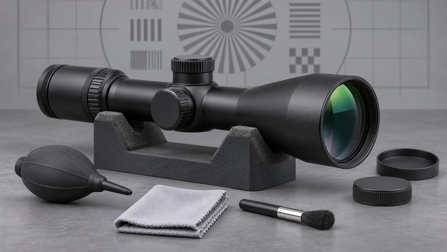
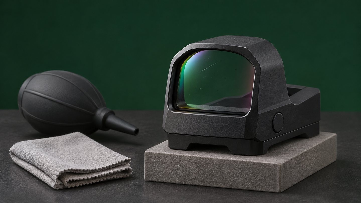
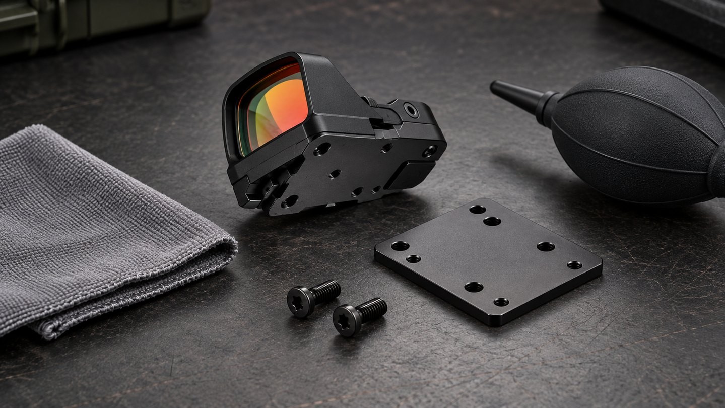
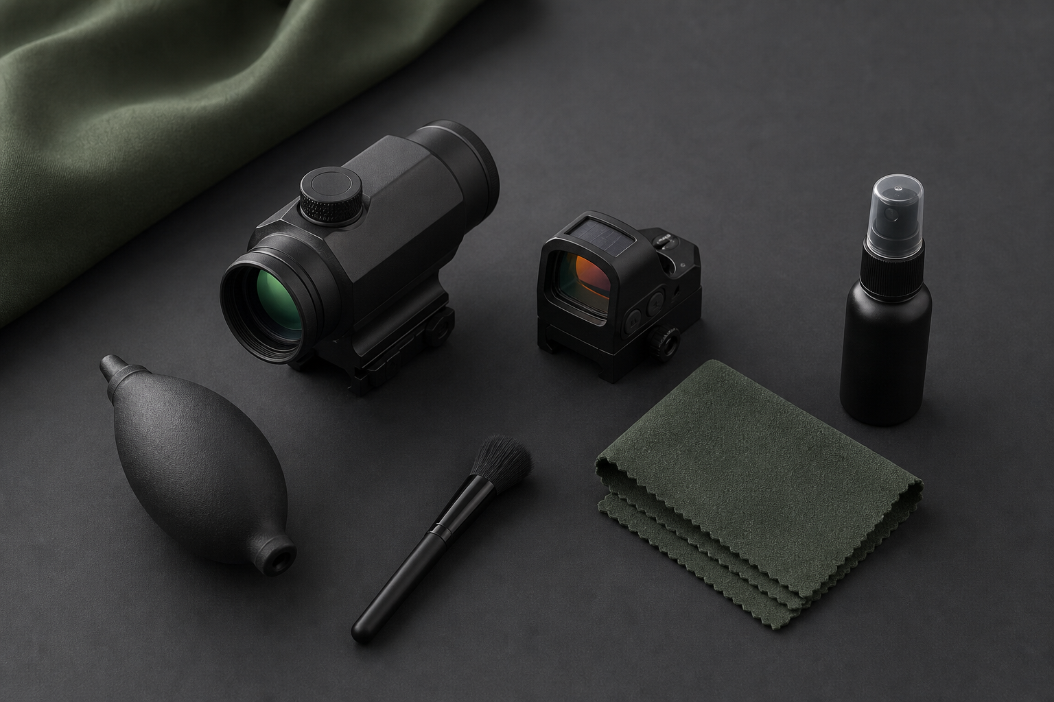
Begin with the least aggressive method. Use clean air from a hand blower or another method allowed by the manufacturer to remove loose particles. A clean, lint-free cloth can lift remaining debris from accessible flat surfaces.
Do not scrape a precision surface with a steel tool, sand a plate flat by eye or use a strong solvent without checking the instructions. Those actions can remove finish, change dimensions, damage a seal or leave new residue.
Solvent advice is especially model-specific. A product manual may permit a certain cleaner for one part while warning against it on another. If the instructions do not state that a chemical is safe for the optic body, sealing material and finish, ask the manufacturer rather than improvising.
Keep liquids away from electronics, battery contacts and optical coatings unless the manual specifically addresses them. The cleaning procedure for a lens is not automatically suitable for the underside of the sight or for a mounting plate.
Check Locating Features and Screw Holes
Many red dot interfaces use posts, bosses, pockets or other locating features in addition to screws. They help position the optic or plate and may share mechanical loads. A part that catches on one of these features can appear almost seated while remaining slightly high on one edge.
Lower the component squarely and confirm that the intended locating features engage without forcing it. If the plate must be pressed, rocked or pulled down by the screws to reach the surface, stop and recheck the exact red dot footprint, orientation and compatibility list.
Inspect screw holes as well. Residue near the opening, damaged threads or the wrong fastener can interfere with clamping. Never chase an uncertain thread with a random screw.
Perform a Dry Seating Check
A dry seating check means placing the verified parts together before final tightening so you can observe how they meet. Follow the manufacturer's procedure and do not omit a required sealing component or other specified layer.
Look around the perimeter under good light. The component should sit in the intended position without obvious rocking. A visible line is not automatically a problem—some housings have chamfers, drainage spaces or designed clearances—but an uneven gap that changes when you press opposite corners deserves investigation.
Do not use the screws as a press to flatten a plate or force an optic over locating posts. If hand seating is not consistent with the instructions, identify the obstruction first.
Oil and Threadlocker Are Not Interchangeable
Oil, grease and threadlocker can change friction during tightening. That means the same indicated torque can produce a different clamping result depending on thread condition. This is one reason generic installation numbers are unsafe.
Follow the exact instruction for whether threads should be dry, pretreated or used with a specified removable threadlocker. Do not coat the broad mating surface with threadlocker. Apply any approved product only where and in the amount directed.
If screws arrive with a factory-applied patch, do not assume more product is better. Check whether the manufacturer allows reuse and whether old material must be removed. Our article on why optic mounting screws loosen explains how friction, settling and hardware fit interact.
Confirm Screw Length Before Final Tightening
A clean interface can still show a gap when a screw is too long and bottoms out before the optic is clamped. The screw may feel tight even though the parts are not.
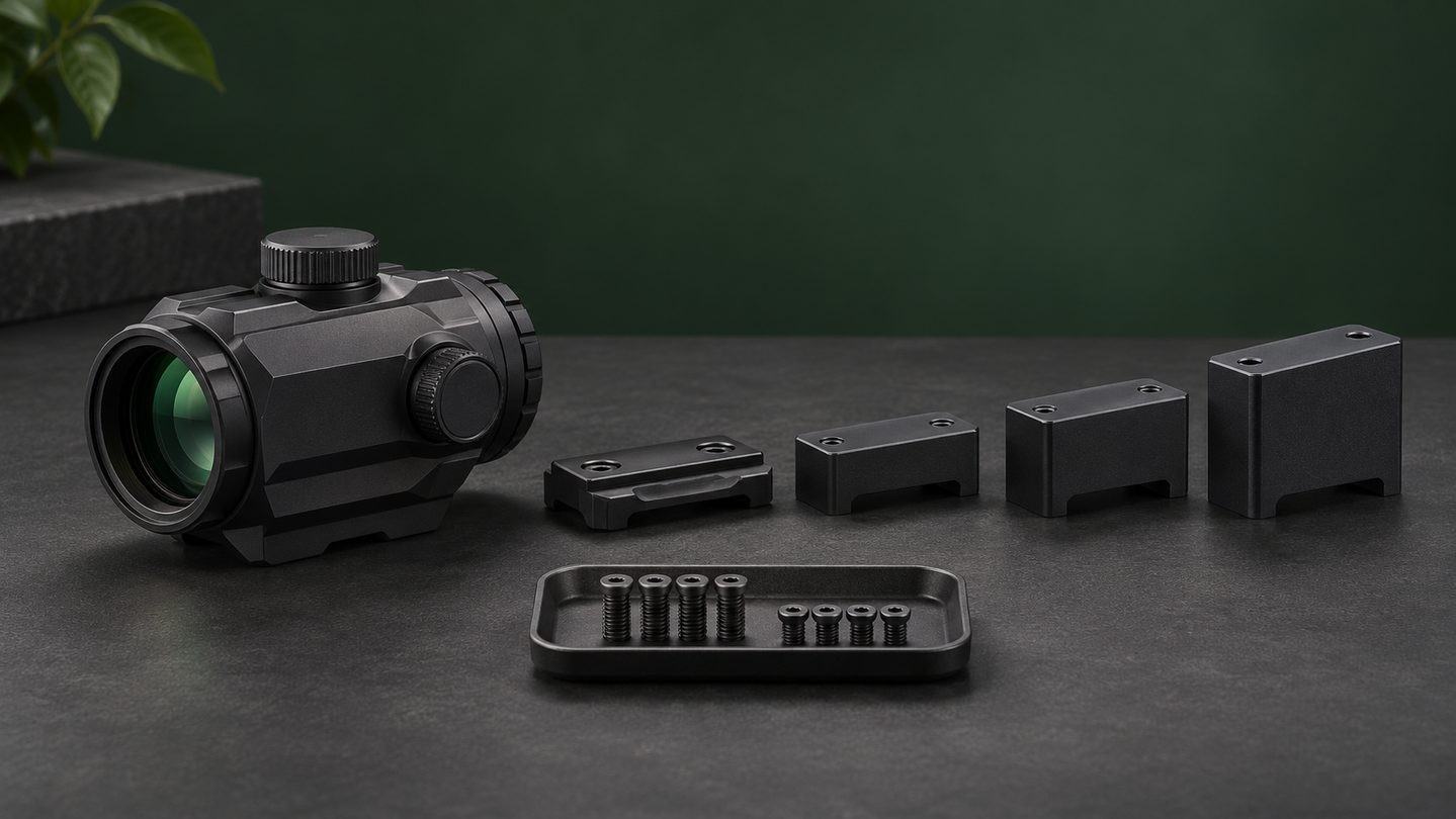
Keep each supplied screw set with its intended layer. Plate-to-host hardware and optic-to-plate hardware may differ in thread, length or head profile. Confirm the exact model instructions rather than selecting the screw that merely starts in the hole.
The separate guide to red dot mounting screw length covers thread engagement, bottoming out and other warning signs in more detail.
When to Stop and Ask for Help
Stop the installation if you find:
- an optic or plate that rocks on a supposedly flat interface;
- a gap that remains after debris and orientation have been checked;
- locating posts that do not enter their matching pockets;
- a plate that bends as screws are tightened;
- damaged threads, a raised burr or a visibly warped surface;
- instructions that disagree about the required plate, seal, screw or thread treatment.
Do not solve these symptoms by adding an unlisted shim, filing a post, sanding a plate or increasing torque. Contact the optic, plate or mount manufacturer with exact model numbers and clear photos. Professional installation is the safer route when a surface or thread may need dimensional inspection.
A Practical Pre-Installation Checklist
Before final tightening, confirm:
- The optic, host interface and any plate are explicitly compatible.
- Every required plate, gasket, seal or spacer is present and correctly oriented.
- Contact surfaces are free of loose debris and unapproved residue.
- Locating features engage without force.
- The parts sit consistently without rocking.
- Each screw matches its assigned layer, thread and length.
- Thread condition and any threadlocker follow the current instructions.
- The manufacturer-specific tightening sequence and torque are available.
Clean, flat contact cannot compensate for the wrong footprint or hardware, but it allows the correct parts to work as designed. Treat surface preparation as part of compatibility verification, then follow the exact instructions for the complete mounting stack.
Browse Red Dot Sights and compare the listed footprint and mounting information before choosing an optic.




Leave a comment