A rifle scope can appear to lose zero even when its internal adjustments are working normally. One possible cause is movement somewhere in the mounting system. The scope may slide inside the rings, a ring may shift on the base, or the base itself may move. These problems are often grouped under the informal term scope creep.
Scope creep should not be diagnosed from one unexplained impact change alone. The useful approach is to document the starting position, inspect each interface and separate visible movement from assumptions about the optic.
What does scope creep mean?
Scope creep is gradual or sudden movement between parts that were intended to remain fixed. It may occur between the scope tube and ring surfaces, between a mount and rail, or between a base and its attachment points.
The direction is not always obvious. A scope can shift forward or backward in the rings, rotate slightly, or remain visually centred while the mount moves on the rail. That is why looking only at the position of the eyepiece is not enough.
Why movement can resemble an optic problem
The scope, rings, base and attachment surface work as one system. A change at any interface can alter alignment. Symptoms may include a changed point of impact, a reticle that appears newly canted, different eye relief, or an adjustment that seems inconsistent.
Those symptoms do not prove internal failure. They also do not prove mounting movement. The goal of inspection is to find evidence before changing several variables at once.
Start with the manufacturer instructions
There is no universal torque value or installation sequence for every ring and base. Fastener size, material, clamp design, surface finish and the scope maker's tube limits all matter. Use the instructions for the exact scope, rings, mount and base.
Do not compensate for suspected movement by applying maximum force. Excessive or uneven tightening can distort a scope tube, bind internal parts, damage threads or create misleading symptoms. Our guide to scope-mount torque explains why one number cannot safely cover every joint.
Look for visible reference changes
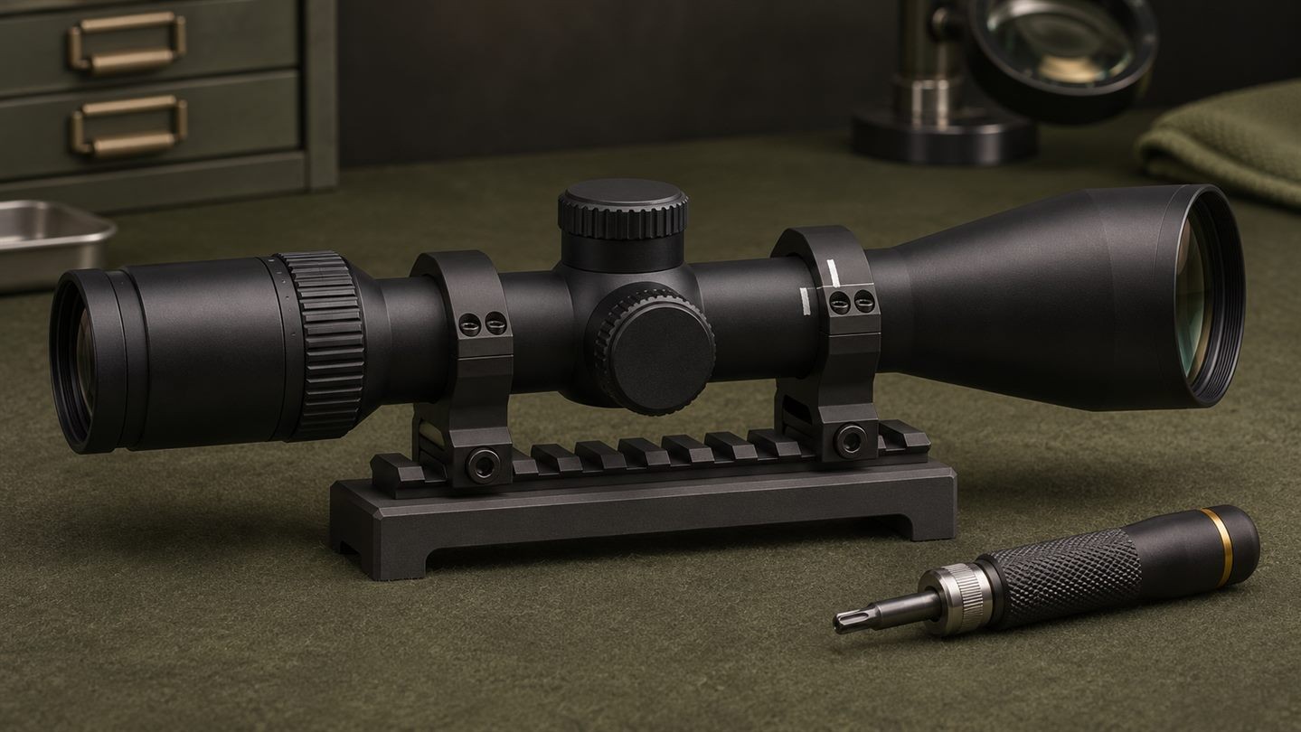
Before loosening anything, photograph the setup from both sides and from above. Include the ring edges, rail slots, clamp surfaces and any existing index marks. Compare these images with earlier photographs if available.
Useful clues include:
- a change in the gap between an eyepiece or turret saddle and a ring;
- a ring edge that no longer aligns with a previous removable witness mark;
- fresh polished areas, scuffs or debris at a clamp interface;
- a mount that is no longer seated against the same rail surface;
- uneven ring-cap gaps that were previously balanced;
- a fastener head or lever that has visibly changed position.
A witness mark is only a reference. It does not secure a joint, replace the correct torque procedure or prove why movement occurred. Use only a removable, finish-safe method permitted by the manufacturer.
Check each interface separately
Treat the mounting system as a chain rather than one object.
Scope tube to rings
Inspect whether the tube has shifted relative to the ring edges. Look for fresh ring marks, a changed eye-relief position or rotation of the reticle. Do not twist or force the scope as a test if the maker does not recommend it.
Rings or mount to base
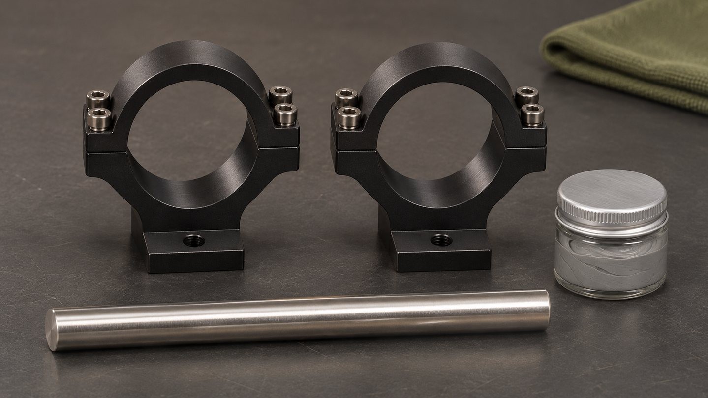
Confirm that cross-bolts, recoil lugs, clamps or quick-detach levers are seated as designed. A clamp can feel tight while being positioned incorrectly. Follow the maker's direction for which surface should be held against the rail during installation.
Base to attachment surface
If the base is separate, inspect it too. A stable scope-and-ring assembly cannot compensate for a moving base. If access requires removing parts or the procedure is outside the user manual, stop and use qualified service.
Common causes to investigate
Movement may be associated with an incorrect tube diameter, mismatched hardware, contaminated contact surfaces, damaged threads, an unsuitable rail profile, a missed installation step, uneven ring alignment or torque that does not match the component instructions.
Sometimes the parts settle after initial assembly. In other cases, a component is simply incompatible. Adding thread treatment without checking the instructions can make matters worse because some manufacturers specify a particular product while others prohibit it or use a different torque value when threads are treated.
For a fuller overview of fasteners, see why optic mounting screws loosen. For ring-specific issues, review scope-ring alignment and over-tightening.
What not to do
- Do not tighten every screw at random.
- Do not assume more threadlocker is safer.
- Do not mix torque values from unrelated products.
- Do not use a witness mark as proof that the optic is defective.
- Do not continue using visibly damaged, bent or cross-threaded hardware.
- Do not disassemble sealed or internal parts of the optic.
Changing multiple settings at once destroys useful evidence. If you loosen the rings, move the scope, adjust the turrets and replace the base in one session, you may solve the symptom without learning which part caused it—or introduce a new problem.
When to stop and contact support
Stop and contact the relevant manufacturer, retailer or qualified installer when you find damaged threads, a bent tube, cracked hardware, a clamp that cannot seat correctly, repeat movement after correct installation, or an internal symptom that remains after the mounting system has been verified.
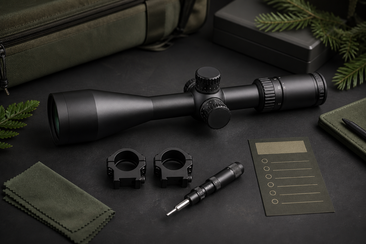
Prepare clear photographs and record the exact scope, mount, rings and base. Note the torque tool and values used only if they were measured. Our optic support-photo checklist can help you document the issue without hiding important details.
A practical inspection sequence
- Stop and make the setup safe before handling it.
- Photograph all mounting interfaces before changing anything.
- Compare eye relief, ring position and removable reference marks.
- Check the exact manuals for every component.
- Inspect one interface at a time for seating, compatibility and damage.
- Correct only the confirmed issue using the stated sequence and torque.
- Document the final position so future changes can be compared.
- Seek service if movement returns or damage is visible.
The key takeaway
Scope creep is a mounting-system diagnosis, not a label for every zero change. Look for physical evidence, check each interface separately and follow the exact component instructions. Careful documentation is more useful than extra force—and it gives support staff a much clearer starting point if professional service is needed.




Leave a comment