Windage and elevation controls look simple, but their arrows are easy to misread. The marking usually describes the intended movement of the point of impact, not the direction the dot appears to travel inside the window while you turn the screw.
That distinction explains many adjustment mistakes. It also explains why copying a direction, click value, or tool choice from a different sight can create more confusion. Red dot controls are model-specific, so the safest approach is to understand the terms first and then use the exact manual for the optic in front of you.
Windage and Elevation Are Two Different Axes
Windage is the horizontal adjustment. It changes the relationship between the sight and the expected point of impact from left to right. Elevation is the vertical adjustment, changing that relationship up or down.
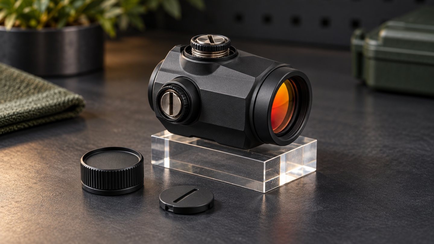
On many compact red dots, the elevation control is on top of the housing and the windage control is on the side. Holosun, for example, documents that arrangement on several current models. It is common, but it is not a promise that every optic uses the same location. A covered screw, recessed slot, or exposed dial may serve the same function, and some housings place controls where the design has room for them.
Identify the controls from the manual before turning anything. Brightness buttons, battery caps, locking screws, and adjustment screws can sit close together on a small housing.
What the Arrow Usually Means
An arrow beside an adjustment is normally a result indicator. If the elevation marking says “UP,” turning in the indicated direction is intended to move the point of impact up. If the windage marking says “R,” the indicated direction is intended to move it right. Aimpoint explains its adjustment screws this way in its official support guide.
The opposite turn should produce the opposite result, but do not assume that clockwise always means up or right. The control’s position, internal mechanism, and viewing orientation can change how a clockwise turn appears. Follow the arrow and wording printed for that exact axis, then confirm the manual.
Some sights combine markings such as UP-R on similar-looking screws. Others mark each axis separately. If a label is worn, hidden by a cap, or ambiguous, stop and find the model documentation rather than guessing.
Why the Dot Can Seem to Move the “Wrong” Way
The adjustment marking describes the intended correction at the target, while your eye is watching a projected dot inside an optical window. Those are different references. When the internal emitter or optical relationship changes, the dot may appear to shift opposite the correction direction relative to the housing.
That apparent reversal is not evidence that the arrow is wrong. It is also why turning the screw while staring through an unmounted optic is a poor way to learn the control. Use the manufacturer’s stated direction and judge the result through a controlled verification process, not by the dot’s apparent travel against the edge of the lens.
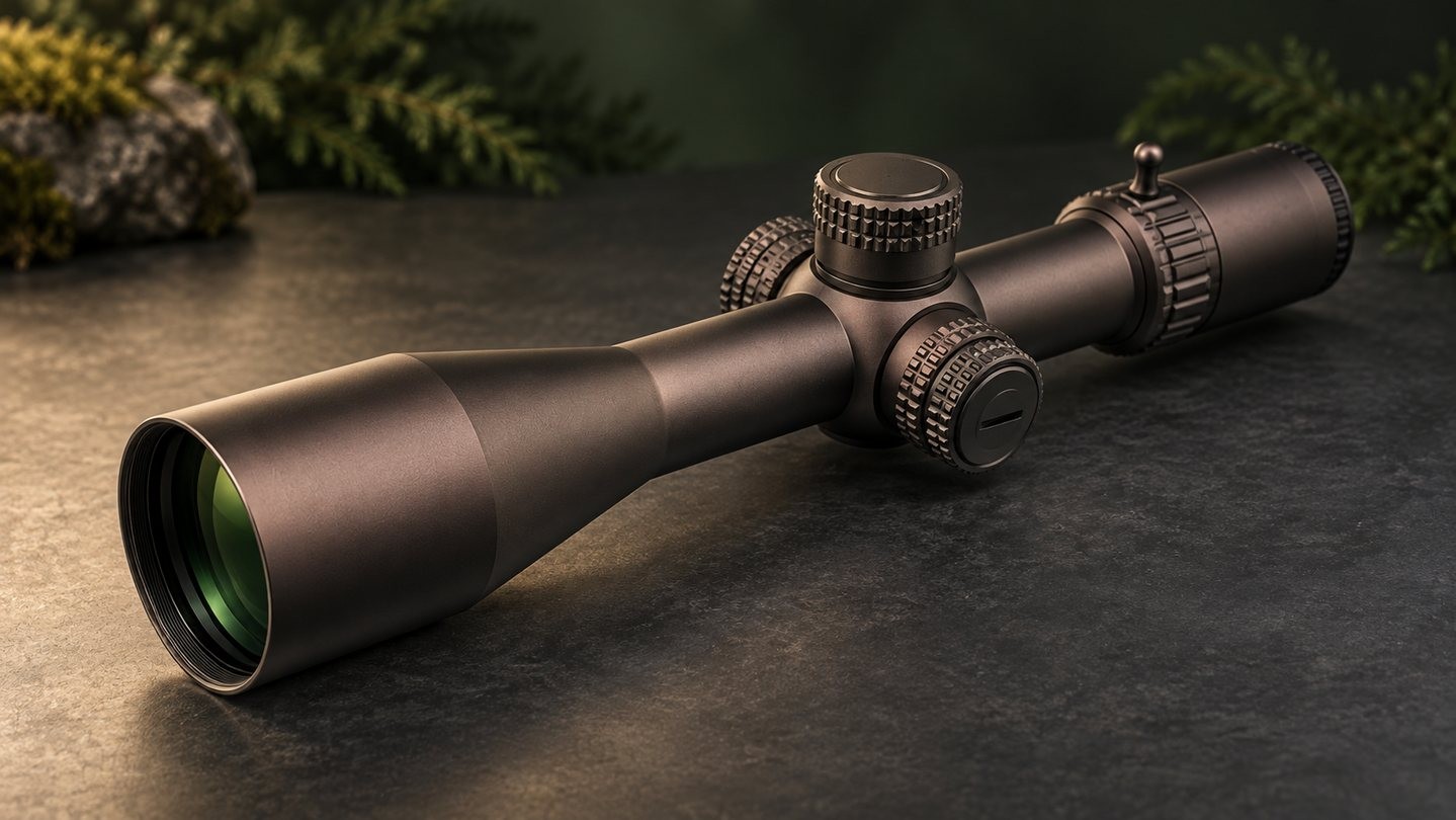
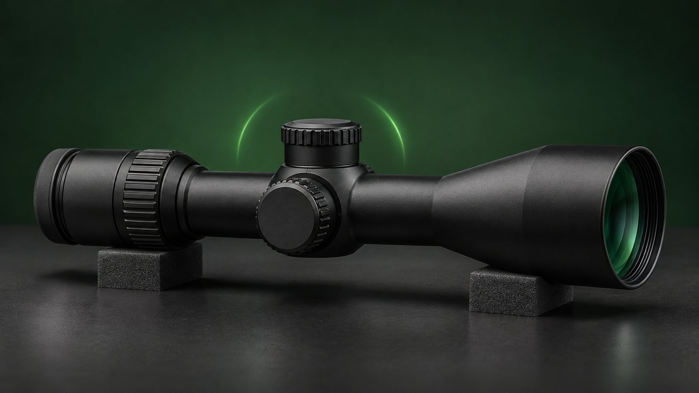
The same source of confusion appears on magnified optics. Our guide to rifle scope turret directions explains the difference between a labeled correction and what seems to move in the field of view.
Click Value Is Not Universal
One click is a defined angular correction, but its value varies by model. A current Trijicon RMR Type 2 product page specifies 1 MOA per click, while Holosun’s ARO-EVO manual specifies approximately 0.5 MOA per click. Those examples show why “two clicks” has no universal meaning.
Read the marking or manual before calculating any correction. A sight may use MOA, MRAD, or another stated increment, and the manufacturer may describe the value as approximate. If MOA and MRAD are unfamiliar, see MOA vs MRAD explained before converting an observed offset into clicks.
A click should also be counted by its tactile or audible detent, not by an arbitrary fraction of a turn. If the control feels smooth on a design that is supposed to click, or if the detents become irregular, document the behavior and consult support.
Use Only the Correct Adjustment Tool
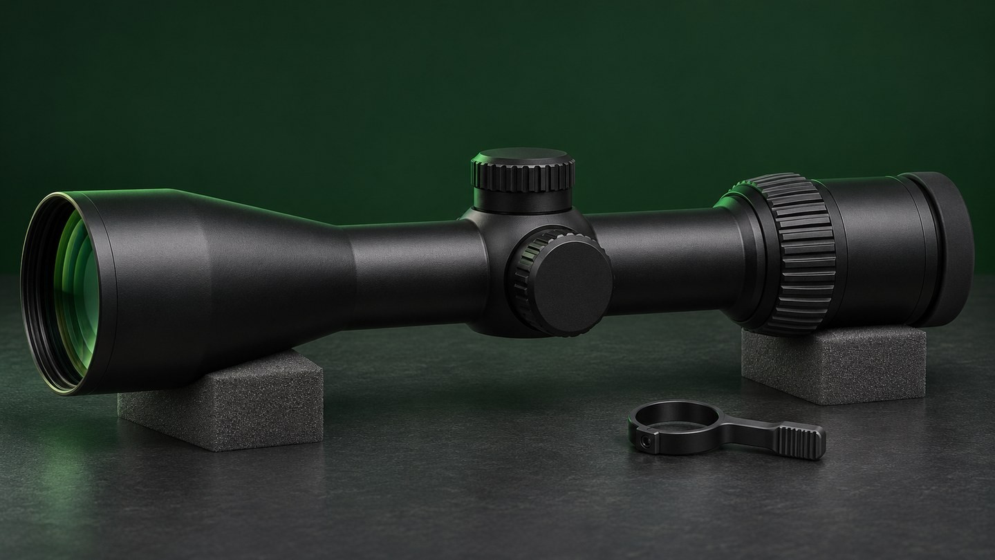
Tool requirements differ just as much as click values. Some recessed slots accept a supplied flat tool. Some designs allow a coin edge or a protective cap to act as the tool. Others specify a Torx or hex key. A tool that fits loosely can scar the slot, slip across the housing, or apply force at the wrong angle.
Remove a protective cap only if the manual directs you to do so, and keep its seal clean. Seat the tool fully, turn gently through one click at a time, and never use pliers on a cap or adjustment body. If the supplied tool has been lost, replace it with the specified type and size rather than choosing the nearest object on the bench.
Do not confuse an adjustment cap with a battery cap. Our comparison of top, side, and bottom battery access can help identify where common battery systems differ from control layouts.
Make Small, Recorded Changes
Before adjusting, record the starting position or take a clear photo of the control. Confirm that the sight and its mount are installed according to their instructions, because a loose interface can imitate an adjustment problem. Change only one axis at a time and write down the direction and number of clicks.
Small, documented changes make it easier to reverse an error. Large uncounted turns make it difficult to know whether the control is near the middle or approaching its mechanical limit. After each change, replace any protective cap correctly and verify the result in a lawful, controlled environment appropriate to the equipment.
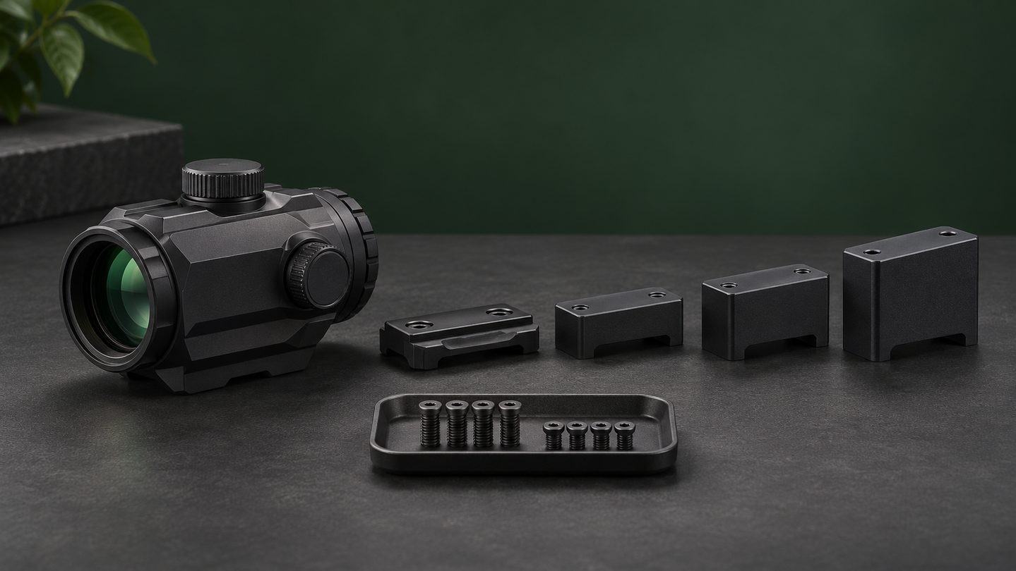
If the apparent correction is inconsistent, inspect the mounting interface before adding more clicks. The article on why optic mounting screws loosen covers common joint and fastener factors without treating adjustment as a substitute for secure installation.
Do Not Force the Mechanical Limit
An adjustment has a finite range. Holosun warns in its current ARO-EVO manual that resistance can indicate the turret has reached its mechanical limit and that forcing it further may cause damage. The exact range varies by sight and should not be inferred from another model.
If the control binds, becomes unusually tight, or stops producing normal clicks, stop turning. Do not use a longer tool for more leverage. A sight that requires extreme correction may have a mount, alignment, compatibility, or installation issue that should be checked before the internal adjustment is pushed farther.
Returning a control to a guessed “center” by counting turns from a hard stop can also stress the mechanism. Use a manufacturer-approved centering procedure only when the exact manual provides one.
When an Adjustment Does Not Hold
A correct adjustment should produce a repeatable result. If the setting drifts, clicks feel inconsistent, or the screw turns without a predictable change, first confirm the sight, adapter, and mount are secure using their specified hardware and torque. Do not compensate for a moving mount by continually changing windage or elevation.
Also check whether the model uses a separate lock that must be released before adjustment and secured afterward. Never assume a nearby screw is a lock. If the manual’s permitted checks do not resolve the problem, keep your notes and contact the dealer or manufacturer. Opening a sealed housing or improvising an internal repair can damage the sight and affect service coverage.
A Practical Interpretation Checklist
- Identify the exact sight model and current manual.
- Confirm which control is windage and which is elevation.
- Read arrows as the manufacturer’s intended point-of-impact correction unless the manual states otherwise.
- Verify the click unit and value instead of borrowing a number from another sight.
- Use only the specified tool and release any documented lock correctly.
- Make small changes, count every click, and record one axis at a time.
- Stop at binding, abnormal resistance, damaged slots, or inconsistent clicks.
- Check the mounting interface before using more adjustment to chase an unstable result.
Once the arrow is understood as a result marker rather than a universal turning rule, red dot adjustment becomes much less mysterious. The exact manual remains the final authority for direction, click value, tool, lock, and mechanical range.




Leave a comment